

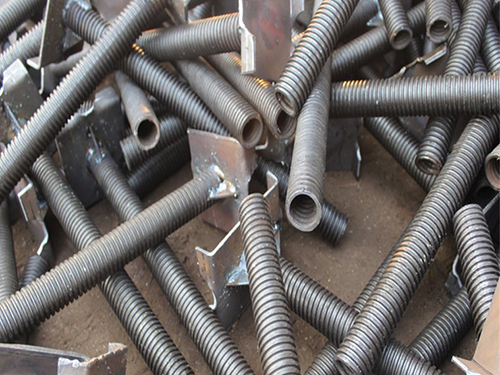
Scaffold U Head Jack
Scaffold U Head Jack is an independent steel structural component mounted at the top of scaffolding vertical uprights for temporary formwork shoring works. It consists of threaded spindle, adjusting nut and U‑shaped cradle head. Each structural part performs separate mechanical functions, and the assembly can complete beam restraint and height adjustment independently without relying on extra scaffolding hardware. Carbon structural steel is adopted as primary raw material. The threaded spindle has two common structural forms, solid round steel bar and hollow seamless steel pipe. Solid spindle owns compact metal texture, high compression and bending resistance, suitable for heavy‑load working conditions such as thick concrete slab support and large‑span temporary shoring. Hollow spindle reduces overall self‑weight while meeting medium‑load bearing requirements, lowering physical burden for manual handling and site installation. Thread sections are mostly processed by cold rolling technology, improving surface hardness of thread teeth and reducing wear generated from frequent nut rotation during repeated turnover cycles. Adjusting nuts are manufactured by forging or casting processes, and their structural completeness determines locking stability under sustained vertical compression load. The U‑shaped cradle head is welded onto the top of spindle. Two parallel side plates form an open clamping groove, which can accommodate timber beams, H20 beams and steel beams, restricting lateral displacement and slipping of horizontal load‑bearing members under concrete pouring loads. Weld seams between U‑head and spindle are critical stress‑bearing positions, and welding continuity shall be maintained during production processing.
Different surface anti‑corrosion treatments are available to adapt to various construction environments. Hot‑dip galvanizing forms dense zinc‑iron alloy protective layers covering spindle, thread teeth and all welding joints. This coating delivers reliable resistance against rainwater, humid air and salt fog erosion, fitting long‑term outdoor exposure and marine transportation scenarios. Electro‑galvanizing produces relatively thin zinc layer on steel surface, applicable for short‑cycle construction projects with low corrosion risk. Paint finishing tends to peel off under thread friction and mechanical impact, so it is rarely adopted for scaffolding hardware with high turnover frequency. Distinct from bottom‑installed base jack, this component is only assembled at the upper end of vertical support uprights. It bears downward loads transmitted from formwork, fresh concrete and horizontal beams, and carries out micro height adjustment to calibrate formwork elevation and flatness before concrete casting.
Core dimensional parameters define its practical mechanical performance. Spindle outer diameter is a critical indicator of load‑bearing grade, and larger diameter corresponds to higher ultimate compression capacity. Effective adjustment stroke sets valid height‑changing range. Excessively exposed threaded segments outside effective stroke scope will reduce structural rigidity and raise bending deformation risk under load. Opening width and inner depth of U‑shaped cradle shall match cross‑section dimension of supported beams. Mismatched dimension will result in insufficient contact area, unstable clamping or beam dislocation. This component is compatible with multiple mainstream shoring systems, including tube‑and‑coupler scaffolding, ringlock and cuplock shoring frames. Dimensional tolerances shall comply with corresponding international technical specifications to guarantee reliable physical fitting with vertical upright tubes during on‑site assembly.
Prior to field deployment, visual inspection and sampling mechanical tests shall be implemented as independent inspection workflows. Visual examination covers spindle bending deformation, surface cracks, welding discontinuity at U‑head connection, thread tooth damage and anti‑corrosion layer peeling. Recycled scaffold U Head Jacks require stricter inspection criteria. Even with intact outer appearance, invisible metal fatigue may accumulate after repeated load cycles and cannot be judged merely through surface observation. Sampling compression tests verify ultimate bearing capacity and anti‑deformation performance. Components with permanent bending, thread slipping and structural cracks must be screened out and scrapped, and shall not be mixed into construction usage. Secondary modification operations including cutting, welding and hole‑drilling on finished scaffold U Head Jack are prohibited. Arbitrary alteration will change original steel section characteristics and weaken overall load‑bearing performance of the component.
Scaffold U Head Jack is designed for cyclic reuse. After formwork dismantling, concrete mortar, dust and foreign residues attached to spindle and thread grooves need thorough cleaning. Impurities trapped inside thread gaps will cause nut jamming and interfere with normal height adjustment and locking effect in subsequent service cycles. Finished components shall be stored in dry and ventilated surroundings, sorted and stacked by specification, avoiding long‑term rain soaking and direct contact with damp soil. Improper on‑site operations include over‑extending threaded spindle, offset load placement inside U‑head cradle, and applying load exceeding rated limit. These improper practices may trigger component deformation, beam slipping and abnormal local stress distribution of shoring frames. As an independent top adjustable load‑bearing unit for scaffolding and formwork systems, its structural integrity and mechanical stability directly influence load transmission state of temporary support structures, and constitute essential preconditions for safe concrete pouring and formwork dimension control.
 BOLGS
BOLGS
-
How do adjustable screw jacks cooperate with scaffolding systems to improve construction precision?
2026-08-19 06:09:35
-
What pre-use inspection items are required for adjustable screw jacks?
2026-08-19 06:09:09
-
What international standards regulate exported adjustable screw jacks?
2026-08-19 06:08:32
-
How to maintain and recycle adjustable screw jacks for repeated use?
2026-08-19 06:07:48
CONTACT
WHATSAPP:+8618630740705
TEL:+8618630740705
Email:331314924@qq.com
Web:https://www.shanchenhardware.com
ADD:Xian County, Cangzhou, Hebei, China